


Navigation

- Products
- Guideway grinding machines
Gantry Guideway Grinding Machine
- Plano millers
CNC plano millerPlano miller- CNC milling machine/machine center
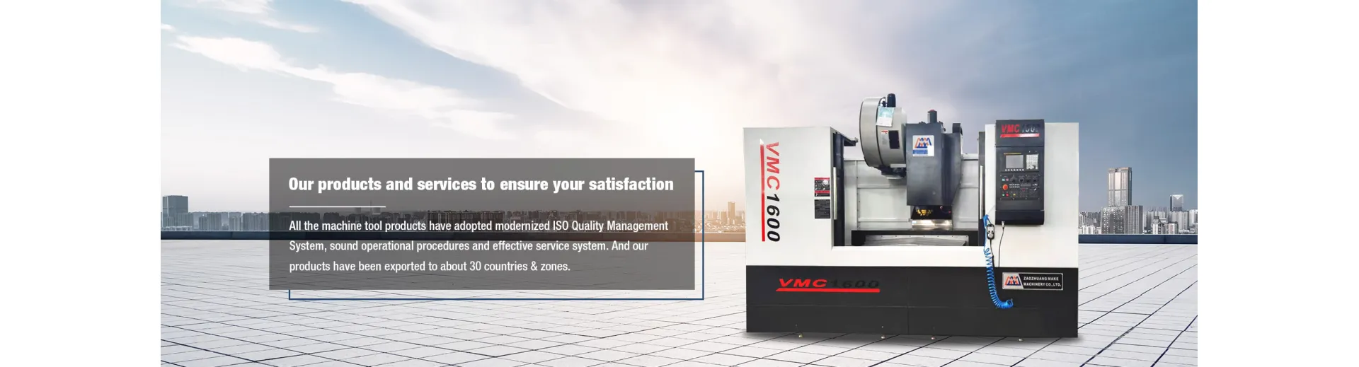
VMC1600 Vertical Machine CenterVMC1570 CNC Milling Machine/CNC Machine CenterVMC400 CNC Vertical Machine CenterVMC1060 Vertical Machine CenterVMC1270 3 Axis Vertical Machine CenterVMC1580 CNC Milling Machine(Machine Center)VMC850/VMC1050 CNC Milling Machine(Machine Center)VMC7132 CNC Milling Machine(Machine Center)- Universal Milling Machine
Universal Swivel Head Milling MachineDrilling/Milling MachineTurret Milling MachineVertical Knee type Milling Machine- Vertical lathe
Vertical Lathe C5112Conventional Double Column Vertical Lathe C52 series- Horizontal Lathe CNC Lathe
Inclined Bed CNC LatheCNC Pipe Threading Machine QK1219CNC Lathe CK seriesCNC Lathe CAK seriesCNC Lathe CTK seriesHorizontal lathe CA Series- Drilling machine
CNC Drilling MachineRadial Drilling Machine- Hydraulic press
Manufacturing Other Special Hydraulic PressHydraulic BendingMandrel PressOthers Hydraulic PressHydraulic C-Frame PressFour Column Sliding Hydraulic Press- Garage equipments
Flywheel grinderCylinder Body and Cover Surface Grinding-Milling Machine- Riveting machine
Customized Riveting MachineRivetless Rivet Connection EquipmentHorizontal Hydraulic Riveting MachinePneumatic Riveting Machine- Air hammer
C41-150 Air HammerC41-75 Air HammerC41-50 Air HammerC41-40 Air HammerC41-25 Air HammerC41-20 Air HammerC41-16 Air Hammer- Saw machine
CNC Saw Machine- Slotting machine
Slotting headLight Slotting machineHeavy Slotting machine- Shearing machine
QC12Y/K Series Shearing machineQC11Y Series Shearing machineQ11 Series Shearing machine- Power press
JH21 series Fixed-table PressJC21S series Fixed-table with Deep Throat PressJC21 series Fixed-table PressJB23 series Open type Inclinable PressJ21S series Fixed-table Press with Open type Deep Throat- Accessories
Milling /boring headClamp kitUniversal Boring HeadAnalysis and solution of vertical lathe failure in Zaozhuang Make Machinery Co., Ltd.
Zaozhuang Make Machinery Co., Ltd. pays great attention to the investigation and analysis of the failure of CNC vertical lathe. The troubleshooting of vertical lathe is a very critical stage. The following should be done:
1. Inquiring into the investigation When receiving the information on the machine site where the fault is required to be eliminated, the operator should first be required to maintain the on-site fault state as much as possible, without any treatment, which is beneficial to quickly and accurately analyze the cause of the fault. At the same time, carefully inquire about the fault indication situation, the fault representation and the background of the fault, and make a preliminary judgment accordingly to determine the tools, instruments, drawings and materials, spare parts, etc. that should be carried on the site to reduce the round-trip time.
2. After the on-site inspection arrives at the scene, the accuracy and completeness of the various conditions provided by the operator must first be verified to verify the accuracy of the preliminary judgment. Due to the level of the operator, there are many cases where the fault condition is unclear or even completely inaccurate. Therefore, after going to the scene, do not rush to handle it, and re-examine the situation carefully to avoid damage to the scene and increase the difficulty of troubleshooting. 3. Fault Analysis According to the known fault conditions, the fault classification is analyzed according to the fault classification method described in the previous section, so as to determine the principle of troubleshooting. Since most faults are indicated, in general, the CNC system diagnostic manual and instruction manual for the machine tool can be used to list the various possible causes of the fault. 4. Determine the cause to investigate a variety of possible causes to find out the real cause of the failure, then the maintenance personnel is a comprehensive test of the machine familiarity, knowledge level, practical experience and analytical judgment.
5. Troubleshooting methods for troubleshooting may be simple. Some faults are often complicated and require a series of preparations, such as preparation of tools and meters, partial disassembly, repair of components, procurement of components, and even The formulation of the troubleshooting steps and so on.
The process of investigation, analysis and diagnosis of the fault of the electrical system of the CNC vertical lathe is also the process of troubleshooting. Once the cause is identified, the fault is almost equal to the elimination. Therefore, the method of fault analysis and diagnosis becomes very important. The common diagnostic methods for electrical faults are listed below.
1. Visual inspection method This is the method that must be used at the beginning of the failure analysis, that is, the use of sensory inspection.
Ask the fault site personnel to carefully inquire about the process, fault appearance and failure consequences of the fault, and may ask multiple times during the entire analysis and judgment process.
Visually check whether the working status of each part of the machine tool is in a normal state (such as each coordinate axis position, spindle state, tool magazine, robot position, etc.), and whether each electronic control device (such as CNC system, temperature control device, lubrication device, etc.) has The alarm indicates that the part is inspected for insurance burnt, the components are burnt, cracked, the wires and cables are detached, and the position of each operating component is correct or not.
Touch can be found under the condition of power failure of the whole machine by touching the installation status of each main circuit board, the plugging status of each plug, the connection status of each power and signal wires (such as servo and motor contactor wiring), etc. s reason.
Power-on means that the power is turned on in order to check for smoke, fire, abnormal sound, odor, and presence or absence of overheating of the motor and components.
2. Instrument inspection method using conventional electrical instruments
For each group of AC and DC power supply voltages, measure the relevant DC and pulse signals, and find possible faults. For example, use a multimeter to check the status of each power supply, and measure the relevant signal state measurement points set on some boards. Use an oscilloscope to observe the amplitude, phase, or even the relevant ripple signal. Use the PLC programmer to find the PLC program. The location and cause of the fault.
3. Numerical control vertical lathe signal and alarm indication analysis method 6 hardware alarm indication This refers to various states and fault indicators on various electronic and electrical devices including numerical control system and servo system, combined with indicator status and corresponding The function description can be used to know the contents of the instructions and the causes and troubleshooting methods. The software alarm indicates that the faults in the system software, PLC program and machining program as described above are usually provided with an alarm display. The possible fault causes and troubleshooting methods can be obtained by comparing the displayed alarm numbers with the corresponding diagnostic instructions manual.
4. Interface status check method
Modern CNC systems integrate PLCs in them, and CNC and PLC communicate with each other in a series of interface signals. Some faults are related to interface signal errors or loss. Some of these interface signals can be displayed on the corresponding interface board and input/output board, and some can be displayed on the CRT screen by simple operation, and all interfaces The signal can be called up with the PLC programmer. This inspection method requires the maintenance personnel to be familiar with the interface signals of the machine and to be familiar with the application of the PLC programmer.
5. Parameter adjustment method
CNC vertical lathe CNC system, PLC and servo drive system are equipped with many modifiable parameters to meet the requirements of different machine tools and different working conditions. These parameters not only match the electrical system to the specific machine, but are also necessary to optimize the machine's functions.
Therefore, any change in parameters (especially analog parameters) or even loss is not allowed; and changes in mechanical or electrical properties caused by long-term operation of the random bed will break the initial matching state and optimization state. This type of fault refers to the latter type of fault in the fault classification section, and needs to be re-adjusted to one or more parameters to be excluded. This method is very demanding for maintenance personnel. It is not only necessary to know the main parameters of the specific system, but also knows that its address is familiar with its function, and it has rich experience in electrical debugging.
6. Spare parts replacement method
When the fault analysis results are concentrated on a certain printed circuit board, it is very difficult to implement the fault on a certain area or even a certain component due to the continuous expansion of the circuit integration. In order to reduce the downtime, the same is true. Under the condition of spare parts, you can replace the spare parts first, and then check the repair fault board. Pay attention to the following problems when replacing the spare parts board. Any replacement of spare parts must be carried out in the event of a power failure.
Many printed circuit boards have some switches or shorting bars to match the actual needs. Therefore, it is necessary to record the original switch position and setting state on the replacement spare board and make the new board the same. OK, otherwise an alarm will be generated and it will not work. Some printed circuit board replacements also require some specific operations after replacement to complete the software and parameters. This requires careful reading of the instructions for the appropriate board. Some printed circuit boards cannot be easily removed, such as boards with working memory, or spare panels, which can lose useful parameters or programs. You must follow the instructions when you have to replace it. In view of the above conditions, before you remove the old board to replace the new board, you must carefully read the relevant information, and understand the requirements and operating procedures before you start, so as not to cause more problems.
7. Cross-transposition method fault board without spare parts, the same or compatible two boards in the system can be interchanged and checked, for example, the exchange of two coordinate command boards or servo boards can determine the fault board or fault. Part. This cross-transposition method should pay special attention to not only the correct exchange of hardware wiring, but also a series of corresponding parameters exchange, otherwise it will not achieve the purpose, but will create new faults causing confusion of thinking, must be considered in advance , design a good software and hardware exchange program, and then exchange and check accurately.
Zaozhuang Make Machinery Co., Ltd. not only handles the lathe maintenance work, but also sells vertical lathes, including CNC double-column vertical lathe CK52 series, CNC double-column vertical lathe CVL series and single-column lathe C5112, etc. With more than 20 years of experience, the company is a mechanical processing company integrating design, manufacturing, assembly, installation, commissioning and after-sales. Welcome new and old customers to come and buy.
- Plano millers
- Guideway grinding machines
